Sunday, 7 June 2015

Idea development for Widening Participation Schools Workshops 2015

Laura and Matthew our ArtLab Undergraduate Research Opportunity Students (UROP) tried out the littleBits kits in preparation for our summer Widening Participation Workshop series at local schools.
They were developing ideas for Creature in a Cup exploring how to create movement and sounds with the Synth kits.

Matt described this as a Zombie in a cup.......

Lauras cat in cup.....


Laura makes some interesting scifi sounds with this one


Animating drawing as cutouts


Friday, 5 June 2015

UROP Student Workshop for laser engraving and cutting

We planned on giving our UROP Summer placement students some time in the ArtLab so they could try some of the equipment (e.g. the laser cutter, 3D printers and 3D scanner), as they are directly involved with the WP workshops that start this coming week. On Wednesday this week they were given some time using the laser cutter. The workshop started with a simple example using a digestive biscuit, on which Laura etched an image. The settings used for the biscuit were the same as for a light engrave for Birch plywood, and the biscuit engraved well.


On reflection, perhaps a biscuit without so much surface texture would give a better output ... we'll keep on experimenting. Note: we placed the biscuit onto a clean sheet of paper before engraving so you could eat the biscuit afterwards.

Laura also cut out a basic keyfob which she had designed with the laserCut software, using fluorescent yellow acrylic:


Setting up the start point for cutting.

Then Matthew created a simple design for a keyfob (for his dog) using Birch plywood. In both cases this illustrates three basic  processes using the laser cutter: engraving, inner cut and outer cut.


Laser Cutter workshop 2

On Tuesday we held another session using the LS3060 laser cutter so that staff members in the Art Department at Reading University could try out the laser cutter. Those present were: Tina, Wendy and Nick. To kick off, there was a short demo to illustrate the basic process in which we engraved some text on a digestive biscuit, just for the fun of it:


The each participant at the workshop created a simple keyfob to illustrate three basic processes: engraving, inner cuts and outer cuts. Unfortunately, nobody took photos of them at the workshop (including me), so we'll have to add them later!

Note: we'll be doing a few more workshops for staff in Dept of Art if anyone reading this is interested. It can be anything from AutoCad basics, 3D Max, laser cutting and etching, and 3D printing.

Monday, 1 June 2015

Unblocking the print head on the CubePro


The CubePro is shown in the image above on the left. The week before last one of the extruders became jammed, which meant that it had to be removed, dismantled and then examining to see where the blockage came from.

Here's what I had to do according to the procedure supplied by Cubify:

1. Level the plate and uninstall filament from the other extruder.
2. Switch off the machine, unplug the circuit board form the rear of extruder #1, and then remove the plate that holds the filament tubes in place.
3. Remove the torx screw holding the extruder in place.

It came apart quite easily, and was easy to dismantle the extruder. The filament had snapped in the filament tube (which I already knew about) but this then became lodged in the extruder itself, and prevented new filament from being installed. The blockage was removed and the extruder refitted.

Then came the fun part of levelling the plate using the setup program. It seemed to work okay, but then you also have to go through the procedure of calibrating the plate (z-gap) so that the filament dispenses evenly, and this took over an hour to get right. The big problem with this is that Cubify rather stupidly chose coarse threads for the machine screws that are used to adjust the print plate. The upshot of this is that you need to turn the screws a microscopic amount to calibrate the plate properly. A fraction of a turn too much and the filament either does not fuse properly, or overlaps too much. It takes a lot of effort of trial and error to get this right.

After finally getting the z-gap correct (well as near as I could get it) I did a test print for a tooth paste dispenser. Here is the result:

[Image to be added later]

I don't think the quality of print is as good as the little Cube 3. It should be better, so I guess it still needs work to get it right.

Friday, 22 May 2015

First Staff Workshop in the ArtLab

Yesterday was the first staff workshop for the ArtLab, and attended by two staff members in the Dept of Art. This was a short (two hour) workshop to introduce the laser cutter, show what it's capabilities are and how to do some basic engraving and cutting. The task was to create a simple keyfob with engraved text, a simple engraved image, and a hole for the keyring. This example was chosen since it demonstrates image and text engraving, inner cut (for the hole) and an outer cut. The idea was demonstrated by Nic:

Nic showing the keyfob idea.


Showing the wooden example I made earlier.
The design on the keyfob was to be a soundwave that we recorded (of the Cube 3D printer making a lot of whirring and clunking noises), converted to a black and white 1-bit bitmap and then imported to LaserCut, plus text underneath.

Christine is importing the image file and adding text to the design to be uploaded to the laser cutter.

The design was then etched onto dark tinted acrylic, and cut out:

Christine's design etched onto tinted acrylic

The acrylic sheet on the laser cutter bed

the next workshop will be in June, and we will be showing the summer placement students (who will be working alongside us on the Creature in a Cup workshops) how to use some of the kit, including the 3D scanner, 3D printers and the laser cutter.


Thursday, 21 May 2015

Driving a Stepper Motor with an ATTiny85 Microcontroller

Tim Sunerton is currently a student in the Art Dept at The University of Reading and wanted to power a number of roller blinds with motors so that they would move up and down. He had already produced one which moved the blind down into a trough of paint and then lifted this back up again and smeared the paint onto a canvas (see Tim's Blind). The blind was powered by a NEMA17 type stepper motor, a motor driver and an Arduino Uno. To attach the motor to the blind, a coupling was fabricated using the 3D printer. 
For the current project (four blinds) and as an exercise in making things smaller I suggested that the blinds could be powered by ATTiny85 microcontrollers, as we don't need all of the ports that the Uno offers. I built a test rig using some stripboard, a voltage regulator (plus a few capacitors) and an ATTiny85. The first image shows the ATTiny85 on the stripboard:


The two wires coming out of the left side of the board connect it to the power supply (in this case a bench power supply @ 12V); the wires at the right power the stepper driver and provide the pulses to drive the motor:


The ATTiny85 was programmed by piggy-backing on an Uno, which I have to say is very easy, although I eventually decided to make a programmer shield for the Uno so that you can just plug in the ATTiny85 directly into the shield and program it without needing to connect any wires. (Note: the stepper motor above was not used for Tim's blind project - just for testing. He used much larger motors for his project).

I made three of these boards and Tim used them in his project. We also had to fabricate 4 new adapters for the blinds. One of the blinds was quite big, and even though Tim used a higher torque motor, the weight of the canvas on the blind pulled the blind down against the force of the motor. This was a bit of a problem, and the solution seemed to be in gearing the motor in some way to increase the torque. After a little thought, I came up with this:


A worm gear that would increase the torque by an order of magnitude, and stop the blind from pulling down. Here's the work in progress as we tested out the motor driver (and killed it, though fortunately had a spare) and programmed the microcontroller for speed and the correct number of rotations:


We used the Uno for this particular arrangement after having blown the original driver. The motor was later attached to the frame using the bracket that we fabricated with the Cube:


Note the lack of hole in the centre of the front mount. Whoops. We later drilled a hole using a pillar drill.


Sense Scanner and Cube Printer


Sense 3D Scanner and Cube 3D Printer

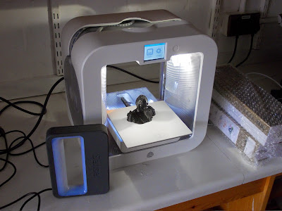
We bought a Sense 3D (made by Cubify) scanner last year at the same time as the 3D printers (also made by Cubify), as it seemed like a good idea to be able to scan objects and them 3D print them. But how good is the scanner, and is it easy to use? That's what we aimed to find out ...

We first tested out the 3D scanner to see how well it performed and how easy it was to use. The sense scanner is handheld and designed so that it is capable of scanning small medium and large objects (such as a car, if you were so inclined). The idea is that you take the scanner in your hand and move around the object carefully scanning the entire object, and then the supplied software will cleverly stitch it all together. In theory. However the scanner is not cordless! Not cordless?! In practice this means that you have to hold your laptop and the scanner and move around the subject, else have a very long USB lead. Even with a reasonably long USB lead, we ended up getting the lead wrapped around the subject (Kate in this instance) making scanning a bit cumbersome to say the least. Come on Cubify, this device should be wireless; it needs to be wireless. Perhaps the next version will be, who knows.

So, we tried scanning a cup on a table as a test scan. The first attempt failed, as we ended up with three cups. The room lighting, it has to be said, does seem to make a difference to the scan. So keep the sunlight away. The next try was by placing the cup onto a box so that it is not flat on the table. This worked a bit better, but perhaps because it was just a bit easier to get around the object. The scan was still somewhat poor, with lots of holes in the final mesh. So we thought that a bigger object might be easier, so Kate volunteered to be the subject. Positioned in a chair, I positioned the scanner about 450cm from Kate and walked very slowly around her keeping the scanner pointed directly at her, as shown in the image preview given by the software. The software shows the subject being scanned, and also shows a circle on the screen to help guide your positioning. It's a bit hard to explain, without some images (which I'll take next time) and is quite difficult to get the position correct as the image moves in the opposite direction to the physical device.

After about 10 minutes of walking around Kate at a snails pace, we ended up with a mesh (I'l add the image of this next time) which didn't look too bad, aside form a few weird artefacts that were produced by the software when Kate moved the cable out of the way to stop it getting tangled (hence the need for WIRELESS!!).

The software for creating the final mesh is not exactly intuitive, and is fiddly and awkward to use. But we ended up with a reasonable model, and so imported it next to the Cubify software that came with the Cube. That is also rather awkward to use (Cubify, you seriously need to employ an HCI person(s), and sort out your crappy interfaces) but we eventually managed to convert it to the correct format and export for the Cube printer:


The image above shows the finished model, which took about 5 hours. I have removed the squiggly bits of filament that covered it. I assume they were remnants form the print process, and not errors. I was quite impressed by the quality of the print (excellent overall) and the printers ability to print overhangs without supports. Here's one more image:

A faithful rendition of kate a la Sense scanner

Close up of the Kate model


Verdict: Sense scanner needs more road testing, and shows promise. The wire is a serious shortcoming, and I am trying to figure out a way of making it wireless - perhaps via some bluetooth hack? The Cube printer is a very nice little machine and I'm really impressed with its performance. Yesterday I printed a bracket (see worm gear post) for a student in the Art Dept for some work he created, and the Cube did a splendid job.